


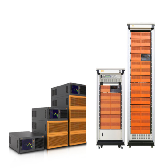


Description
main function
- Battery cell charging or charging system
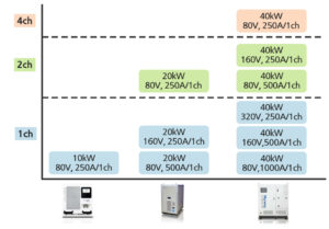
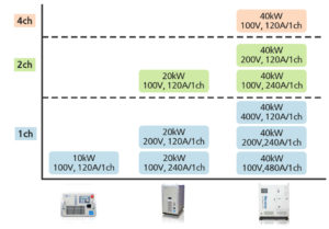
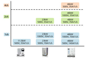
- Up to four 10kW base units are built in a direct parallel structure to supply the charging system (80V/200A, 100V/120A, 400V/30A, and 500V/35A total of four model lineups)
- Inverter circuitry enables power regeneration by returning power to the system through regenerative function
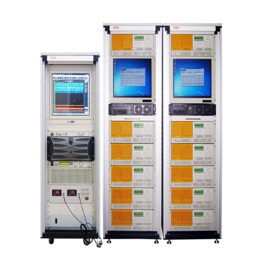
Implementing the role of power supply and electronics for - one unit of 10kW
- high precision measurement function
- Parallel architecture provides capacity-changeable systems
- Fast Response Speed (3 ms)
- Multi-channel configuration based on consumer needs
- Low voltage ripple and noise enable precision charging and discharging
- Compositioned with a general anti-temperature and anti-bulb antifreeze to provide data acquisition
- Battery Module/Pack Charging/Discharging/Rest Features
- Measuring Battery Module/Pack temperature and setting the power cut-off function accordingly
- THD<5%, Power Factor>0.95, Recycling Efficiency>90%
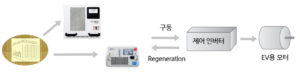
regenerative drive circuit diagram
회생 구동 회로도

- Separate voltage/current settings can be set for each channel, and multiple channels can be configured through separate consultation.
- Data can be obtained from voltage, current, resistance, power, temperature, etc.
- Various operating modes (CC mode, CV mode, CP mode, Constant Voltage-Limit Current mode, Waveform Current mode, DCIR mode
- Charge (V/A), Discharge (A/R/P), Recycle (Rest), Capacity (Ah), Start Time and End Time (Sec) Setup and Temperature (°C) Setup Functions
- Over voltage protection (V), Under voltage protection (V), Over current protection (A), Over property protection (°C), Over capacity protection (Ah),
Provides various protection functions such as Channel data in data logger (Option), ectionV /++V protection (V), and + (I /-ΔI protection (A). - BMS communication interface provided
- Ability to implement graphs and store data for each channel
application field
- Battery Module/Pack manufacturer’s product Charging/Discaring/Rest Test
- EV Battery Module Test (Battery Charge System for R&D, Battery Charge System for Safety Test, Battery Charge System for Production Line)
- Electric Scooter Test
- Electric Bike Test
- UPS Test
- Energy Storage Battery Test
- Lead-Acid Battery Test
- Application of Module/Pack testing applications for windmills, Automatic Guided Vehicle (AGV), cranes, smart meters, power vaccines, heavy equipment vehicles, toy batteries, power tools, tanks, railways, hybrid buses, FCEVs, etc.
- Applied to testing of modules & packs for backup power on military, medical, solar, robot and electronic circuits
- Analysis of Battery Module/Pack characteristics
- Battery Module/Pack voltage balance test
- Overcharging/Undercharging, Testing
- Battery Module/Pack Reliable/Durability/Lifetime/Burn-in Test
Product Configuration Diagram – 80V/250A
Product Configuration Diagram – 100V/120A
Product Configuration Diagram – 400V/30A

Product Configuration Diagram – 500V/35A
Example of using power for motor control inverter for “EV”