


Hello, I’m the web master. Today I’m going to post about the Photonic Doppler Velocimetry (PDV) application from Quantifi Photonics.
The basic components and specifications of the PDV system.
- Laser -> ex) LaserPXle-1054-2
- Doppler module -> ex) DopplerPXle-1001-1
- Optical to Electronic converter -> ex) O2EPXle-1101
- Probe
- Real time scope -> ex) 8Ghz, over 20 Gs/s , DSO
- Data processing algorithm
Before listing your configuration, we would like to share more information about PDV. We can also communicate this reading to end users to give them a deeper understanding of the advantages of our PDV system.
The following are examples and configurations for using PDV modules and matching real-time ranges.
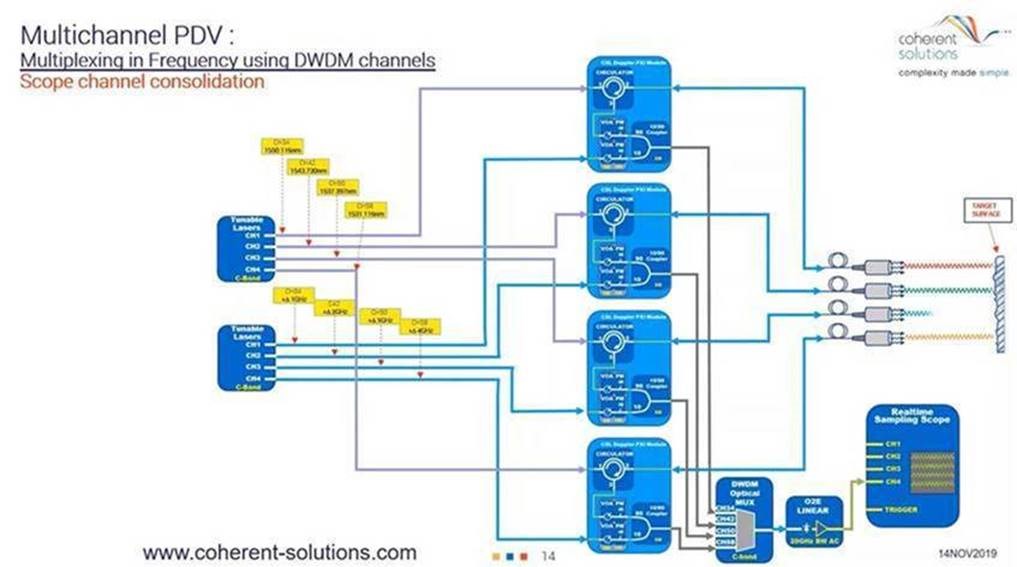
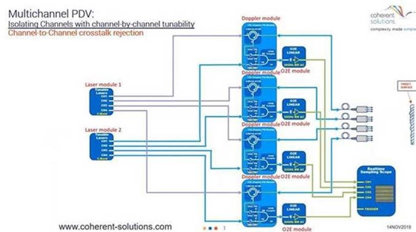
The four-channel heterodine PDV system schematic is as follows:
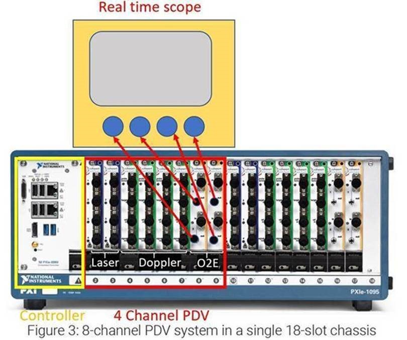
The following picture shows the shape of the 19-inch PXI chassis.
We suggest setting up heterodine. Customers can use a 25GS scope to test speeds up to 20 km/s. There are also several advantages to using heterodine settings.
First, a separate narrow line width laser for target and reference values allows the O2E converter to intentionally offset the bit frequency to a higher value near the oscilloscope’s bandwidth and sampling limits used to capture bit frequency waveforms. By adjusting the frequency of the target laser to a point lower than the reference laser, the resulting bit frequency of the high-speed event that reflects the target increases the target reflection frequency. Within the combined bandwidth and sample rate limits of the O2E converter and oscilloscope, the identifiable bit frequency is by default twice. This is because the bit frequency moves from the initial high value to 0 Hz as the target rate increases, and then passes through 0 Hz until the maximum bandwidth-sample-lay is reached.The te limit has been reached on the opposite side. This upward movement offset method effectively doubles the maximum speed events that can be measured on the PDV system without increasing the cost of the oscilloscope or O2E solution.
For example, for an 8GHz, 25GSPS real-time scope. (Tek real-time scope)
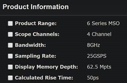
It has an 8GHz bandwidth and a memory depth of 62 with a 25GPS sampling rate.5Mpts.
An 8GHz oscilloscope with a sampling rate of 25G sample/s has a Nyquist limit of 12.5GHz, which is approximately equal to the upper limit of 9.688 km/s (12.5*775 m/s) when using the homodine setting. Even if the bandwidth is rolled off, these oscilloscopes have enough signals to see the Doppler frequency up to 12GHz, allowing you to measure a speed of approximately 9.3 km/s. In the heterodine setting, the maximum speed can be doubled by placing the reference laser relative to the target laser so that the bit frequency passes through zero to -12.5 GHz.
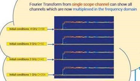
Second, ITU-TG by using independently adjustable laser sources for C-band and L-band.Each target and reference laser pair can be flexibly assigned to a typical ITU grid channel associated with the 694.1 standard, and the multi can be isolated by combining common accessories such as DWDM optical Mux and Demux passive components.You can use multiple PDV channels at the same time. This allows a single oscilloscope channel to capture multiple channels by literally floating reflections on each channel in a different time frame of time. It also prevents cross-talk between different channels during the experiment.

Finally, if you use a dedicated tuning laser for each target and reference laser combined with an inline power meter and attenuator inside the Doppler instrument, you can optimize the relative mixing level of the reflected signal for each channel. Channels can have very different reflections on each other, making it easy to use power monitoring in real time for all target reflective power and all reference laser power before mixing is critical for ease and consistency of setting before shot/impact events in PDV experiments.
Another recommendation is to add the ability to turn off the laser dider, which allows the user to measure relatively low speeds.
Laser sources based on ITLA multi-source contracts use a technique commonly known as “dithering” to increase frequency stability. Dithering can help achieve frequency stability, but in heterodine settings, the phase of the laser can wander relative to each other, which can lead to uncertainty in terms of relative frequency. To eliminate uncertainty and provide higher fidelity, Coisic Solutions provides custom operating modes for adjustable lasers, known as “whispering modes” that help disable the dithering function and help the system reach the lowest possible speed to measure.
Below are the most common settings that support measurements of up to 20 km/s on 4-channel PDV systems.
| LaserPXIe-1054-4-FA X2 | PXIe module for PXIe chassis containing 2 X C-Band (1527.605 nm -1568.773 nm), tunable lasers. Standard output power variant (8dBm to 13dBm). FC/APC connectors |
| DopplerPXIe-1001-1-FA X4 | PXIe module for PXIe chassis containing 2 VOA’s and inline Power meter, Single mode fibre, circulator and 10/90 coupler. FC/APC Connectors. |
| O2EPXIe-1101-2-FA X2 | PXIe module for PXIe chassis containing 1 x AC-coupled Photoreceivers. Operating wavelength 950 – 1650nm. 3dB Bandwidth 25GHz typical. Conversion gain 700V/W min, 900 V/W typical. Single mode fiber. FC/APC connectors. |
| NI-PXIe-1078 | NI PXIe-1078, 9-slot PXIe chassis, 1 slot for controller, 8 slots available for modules |
| NI-PXIe-8821 | NI PXIe-8821 Controller |
TEL : (82) 031-708-7170 Email : mwkim@laonuri.com